Electrical Resistivity Imaging (ERI) also known as resistivity survey is one of a number of methods used in geophysics.
Electrical resistivity imaging is one of the versatile method in ground investigation especially in engineering and environmental geophysics.
The electrical resistivity technique is a useful method for characterizing the subsurface materials in term of their electrical properties.

How It Works?
The general principle of resistivity survey is by injecting of current via pair of electrodes and then the resulting potential field is measured by a corresponding pair of potential electrodes.The Basic Principle of Resistivity Survey

Modern Acquisition
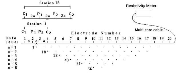
The modern acquisition system for electrical resistivity imaging survey involving multi-electrode system.The array of regularly spaced electrode are connected to a central control unit via multi-core cables during the measurement.
In the example below, the spacing between adjacent electrodes is “a”. The first step is to make all the possible measurements with an electrode spacing of “1a”.
In the example below, the spacing between adjacent electrodes is “a”. The first step is to make all the possible measurements with an electrode spacing of “1a”.
For the first measurement, electrodes number 1, 2, 3 and 4 are used. Notice that electrode 1 is used as the first current electrode C1, electrode 2 as the first potential electrode P1, electrode 3 as the second potential electrode P2 and electrode 4 as the second current electrode C2.
For the second measurement, electrodes number 2, 3, 4 and 5 are used for C1, P1, P2 and C2 respectively. Then,the measurement will continue with bigger electrode spacing for deeper depth.
There are a few array commonly used in data acquisition:
1) Wenner
2) Wenner-Schlumberger
3) Dipole-dipole
4) Pole-dipole
5) Pole-pole
For the second measurement, electrodes number 2, 3, 4 and 5 are used for C1, P1, P2 and C2 respectively. Then,the measurement will continue with bigger electrode spacing for deeper depth.
Types of Array
There are a few array commonly used in data acquisition:
1) Wenner
2) Wenner-Schlumberger
3) Dipole-dipole
4) Pole-dipole
5) Pole-pole
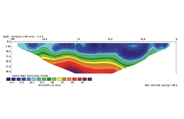
Deliverables / Results
Advanced data processing using specialist inversion software is used to produce a high resolution image of the variations in ground resistivity with depth.The model is contoured using a color scale to produce a two-dimensional cross-sectional model of ground resistivity (figure below).